A radio link depends on compatible antenna polarization and clear radiation paths as the aircraft moves.
Why antenna polarization and orientation affect video quality
A link can fade during a turn even if the aircraft is barely farther away. Polarization, radiation pattern and airframe shielding can all contribute.
Linear and circular polarization
Linear polarization describes the electric field's orientation, such as vertical or horizontal. Linear antennas are strongest when aligned; rotating one relative to the other can increase loss. Circular polarization has a rotating field, but both ends should have compatible handedness. Assess mixed types using actual antenna specifications.
Pattern and mounting
An omnidirectional antenna is not equally strong in every three-dimensional direction. It has weaker angles, and batteries or metal mounts can block parts of its pattern. A directional ground antenna needs accurate pointing. Coax loss and loose connectors may hide the real cause.
Peak gain concentrates radiation; it does not create transmitter power. Verify operating frequency, connector and impedance, and polarization before replacing an antenna. A mechanically fitting connector is not proof of RF compatibility.
Diagnose with repeatable movement
Record signal and video while rotating or banking the aircraft in a controlled setup. Keep frequency and antenna positions consistent when comparing. Inspect orientation, polarization, connector seating and the clear view around each antenna. Distinguish a predictable attitude-related fade from random interference.
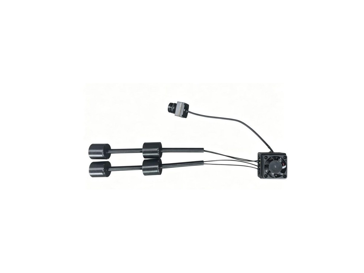
Proper placement and compatible polarization protect the link margin already available.